
ADC Voltage References: Noise, Decoupling and Drive
Every error in the reference is an error in every reading, multiplied by the reading itself.
- Lesson 7 of 7
- Advanced
A converter does not measure volts. It measures a ratio: your input divided by its reference, scaled to the number of codes. Every property of the reference therefore appears in every reading, multiplied by the reading itself.
That last clause is the one that matters. Reference error is not an offset that calibration sweeps away. It is a gain error, and it grows with the thing you are measuring.
Quick answer. The reference sets the full-scale range, so a fractional error in it is the same fractional error in every result. Its drift with temperature is usually the dominant term, its noise has to stay below half a code, and a SAR draws real current from it during every conversion, which means it needs a local capacitor and a source that can recover between bit decisions.
Reference error is gain error
The conversion is:
code = (V_in / V_ref) · 2^NChange V_ref by a fraction δ and every code changes by the same fraction. For the converter this course uses, full scale of 2.38 V on a 3.3 V reference is 2954 codes. A reference that drifts 10 ppm per degree, over an operating range of 60 °C:
drift = 10 ppm/°C × 60 °C = 600 ppm
error at full scale = 2954 × 600×10⁻⁶ = 1.77 codes
error at half scale = 0.89 codes
Two codes at the top of the range and one in the middle. Compare that with an offset error, which would be the same everywhere: this one has a shape, and that shape is what makes it survive a single-point calibration.
The same arithmetic in reverse is how you specify the part. If you can afford one code of gain error over the temperature range, you need:
1 / 2954 = 339 ppm over 60 °C = 5.6 ppm/°CWhich is a precision reference, not a cheap one. Working that number out before choosing is the difference between a specification and a hope.
Noise in the reference is noise in the reading
Reference noise within the measurement bandwidth adds directly. The budget is the usual one, half a code:
allowed noise = 403 µV RMSFor a 12-bit system that is enormous. Almost any reference is quiet enough, and this is simply not a constraint worth agonising over.
It becomes the dominant constraint very quickly as resolution rises. One code of a 24-bit converter on 3.3 V is 197 nV, so the same half-code budget is under a hundred nanovolts, and now the reference's low-frequency noise, which is specified in microvolts peak-to-peak from 0.1 to 10 Hz, is the whole problem. This is why precision references exist as a product category and why their datasheets lead with a noise plot rather than an initial accuracy figure.
The filtering trick worth knowing: broadband reference noise can be reduced by a low-pass filter at the reference output, but the filter has to be arranged so it does not spoil the reference's ability to supply the converter's current pulses. That is a genuine design problem with published solutions, not something to improvise.
The converter draws current from it
This is the part that surprises people who think of a reference as a number.
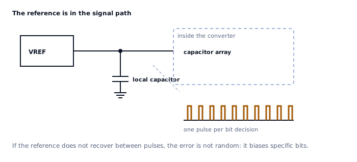
A SAR's capacitor array connects to the reference during every bit decision. Each connection is a charge transfer, so the reference sees a burst of current pulses, one per bit, for the whole conversion. The reference has to recover between them, because the next decision is made against whatever voltage it has recovered to.
If it has not recovered, the error is not random. The decision for bit k is made against a slightly sagging reference, which biases that bit in a consistent direction, which shows up as differential non-linearity at specific code boundaries. A reference problem therefore looks like a converter linearity problem, which is a thoroughly misleading symptom.
Three things follow:
- A local capacitor at the reference pin is not optional. The datasheet
will specify a value and often an ESR limit, because the capacitor is what actually supplies the pulses. Where to put it is the same question as for any decoupling, answered in the placement lesson of the power integrity course.
- A buffered reference needs a stable buffer. An amplifier driving several
microfarads is the capacitive load problem again, and solving it with a series resistor reintroduces a voltage drop under the average reference current.
- Sharing a reference between converters is a decision, not a saving. The
pulses from one converter land on the reference the other is using.
The case where none of this matters
If the sensor is excited from the same reference that the converter uses, the reference cancels out of the measurement entirely.
A resistive bridge excited at V_ref produces an output proportional to V_ref. The converter divides by V_ref. The ratio is independent of V_ref, so drift, initial accuracy and slow noise all disappear, and what is left is only the reference's behaviour over the duration of a single conversion.
This is called ratiometric measurement, and when the sensor allows it, it turns the most expensive specification in the system into one that barely matters. It is the first question to ask about any bridge, resistive divider or potentiometric sensor, and it is frequently answered by accident rather than by design.
What it does not fix: noise fast enough to differ between the excitation and the conversion, and any reference error that affects the two paths differently.
A short checklist
| Question | Why |
|---|---|
| Is the measurement ratiometric? | If yes, most of this lesson stops applying |
| What is the drift specification over your actual temperature range? | It is a gain error and it scales with the reading |
| What does one code cost in ppm? | Turns a code budget into a reference specification |
| Does the reference meet the converter's capacitor and ESR requirement? | The capacitor supplies the conversion pulses |
| Is the reference shared? | Then conversions interact |
| Is a buffer in the path? | Then the capacitive-load trade applies |
What comes next
Lesson 8 goes back to the input and asks a different question: what happens to interference that is nowhere near your signal, which turns out to be much more dangerous than interference that is.
Sources and further reading
- Texas Instruments: Precision voltage references (SLYT183) — journal article, initial accuracy, drift, noise and how each one reaches the result.
- Texas Instruments: Voltage-Reference Filters (SBVA002) — application bulletin, reducing reference noise by filtering without spoiling its ability to supply current.
- Microchip: AN693 Understanding A/D Converter Performance Specifications — application note, gain error and linearity and how a reference contributes to both.
- Texas Instruments: Understanding Data Converters (SLAA013) — application report, the reference as part of the transfer function rather than a supply.