
How a Boost Converter Works, and What It Costs
Output voltage goes up. Input current goes up more.
- Lesson 2 of 10
- Intermediate
A boost converter produces an output higher than its input. People reach for it expecting something like a transformer: 5 V in, 12 V out, job done.
The part that surprises people is the input current. A boost does not create energy, so if the output voltage is higher, the input current must be higher still. That single fact explains most boost design problems.
Quick answer. A boost stores energy in an inductor while a switch connects it to ground, then opens the switch so the inductor's voltage adds to the input and pushes current through a diode into the output. Because power in must exceed power out, the input current is larger than the output current by at least the voltage ratio, and usually more once losses are counted.
The two states, again
The topology is almost the buck rearranged. The inductor sits directly across the input, the switch pulls its far end to ground, and a diode or synchronous rectifier carries current from that node to the output capacitor.
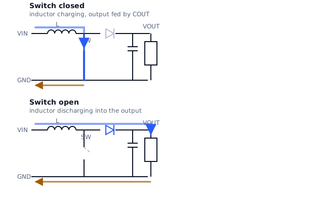
Switch closed. The inductor is connected between the input and ground. It has the full input voltage across it, so its current ramps up and energy accumulates in its field. During this entire time the output receives nothing from the inductor. The load is supplied by the output capacitor alone.
Switch open. The inductor current has to keep flowing. The only path left is through the rectifier into the output. To push current into a higher voltage, the inductor end rises above the output, and the inductor's stored energy delivers charge to the capacitor and load.
The asymmetry is the opposite of the buck. Here the output current is chopped, delivered only during the off-time, and the input current is continuous. That is why boost converters have relatively easy input capacitors and demanding output capacitors, and why their output ripple is usually worse than an equivalent buck.
The transfer function and the current
Apply the same steady-state argument as lesson 1. The current rise during the on-time equals the fall during the off-time:
VIN · t_on = (VOUT − VIN) · t_off
which rearranges to:
VOUT = VIN / (1 − D)
For 5 V in and 12 V out:
1 − D = VIN / VOUT = 5 / 12 = 0.4167 D = 0.5833
The switch is closed about 58 % of the time.
Now the part that matters. Ignoring losses, power in equals power out:
VIN · I_IN = VOUT · I_OUT
So for a 1 A load at 12 V from a 5 V input:
I_IN = (12 × 1) / 5 = 2.4 A
The input current is 2.4 times the output current. Add a realistic 90 % efficiency and it rises to about 2.67 A. The inductor carries this input current continuously, not the 1 A you are delivering.
This is the number that catches people out. An engineer sizing the inductor for "1 A output" picks a 1.2 A part and wonders why it runs hot and saturates. The inductor in a boost carries the input current, which is always the larger one.
What it costs
Three consequences worth knowing before choosing a boost.
The source has to supply it. A USB port, a coin cell or a current-limited supply has to deliver that higher input current, not the output current. A boost that works on the bench with a laboratory supply can brown out on the intended source.
The duty cycle has limits. As the required ratio grows, D approaches 1 and the off-time becomes very short. The rectifier gets less and less time to transfer the energy, so the peak currents climb steeply. Large step-up ratios with a single boost stage become inefficient and eventually impractical, which is why big ratios usually use a different topology.
There is a path from input to output when the switch is off. Through the inductor and the rectifier, the input is connected to the output whenever the converter is not switching. A boost cannot disconnect its load, cannot limit inrush at startup by itself, and cannot protect the load from an input overvoltage. If your design needs any of those, they are separate circuitry.
Why "it just multiplies voltage" is the wrong model
The useful mental model is not a voltage multiplier but a bucket brigade. Each cycle, the inductor picks up a packet of energy from the input and hands it to the output capacitor. The output voltage is whatever results from balancing the rate those packets arrive against the rate the load removes charge.
That model predicts the behaviours the multiplication model misses:
- Output ripple depends on how much charge the load removes between packets,
so it worsens at heavy load and at low frequency.
- Transient response is limited, because the converter cannot deliver extra
energy until the next cycle's packet arrives.
- A load step that outpaces the inductor leaves the output capacitor to cope
alone until the loop responds.
When a boost is the right answer
It is the right tool when the input is genuinely always below the output and the current is modest: a sensor rail from a battery, a bias supply, a backlight string, an auxiliary rail from an existing low rail.
It is the wrong tool when the input can cross the output, which is lesson 3, or when the ratio is large enough to push the duty cycle towards its limit.
What comes next
Lesson 3 takes the case the boost cannot handle: an input that is sometimes above and sometimes below the output, which is the normal situation with a battery.
Sources and further reading
- Texas Instruments: Basic Calculation of a Boost Converter's Power Stage (SLVA372) — application report, duty cycle and current relationships for the boost power stage.
- Analog Devices: Selecting the Right Inductor Current Ripple — technical article, inductor current and ripple across topologies.
- Texas Instruments: LM5156 boost controller datasheet — datasheet, worked design procedure for a boost power stage including duty-cycle limits.