
Buck-Boost: Three Different Circuits With One Name
The requirement decides the topology, and they are not interchangeable.
- Lesson 3 of 10
- Intermediate
A lithium cell runs from about 4.2 V charged to about 3.0 V empty. You need 3.3 V. For the first part of the discharge you need to step down, and for the last part you need to step up.
Neither a buck nor a boost can do that. This is the situation buck-boost exists for, and "buck-boost" is not one circuit. It is a family, and the members behave differently enough that picking the wrong one is a real design error.
Quick answer. Use a buck-boost when the input can be both above and below the output. The inverting topology is the simplest and gives a negative output. The non-inverting four-switch type gives a positive output and is what most modern integrated parts use. Single-inductor SEPIC and similar topologies trade efficiency and complexity differently. The requirement decides, not preference.
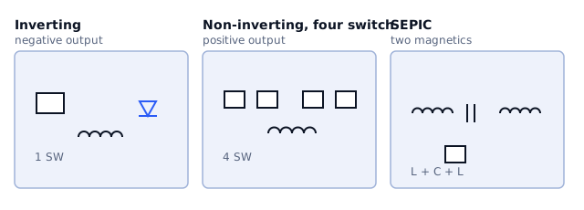
The three you are likely to meet
Inverting buck-boost. The classic textbook circuit. One switch, one inductor, one diode, and an output whose polarity is inverted relative to the input. From +5 V it gives you −5 V, or −12 V, with a magnitude set by duty cycle.
It is genuinely useful when you need a negative rail, which analog front ends often do. It is useless if you wanted +3.3 V, and every so often someone builds one expecting a positive output. Its switch also has to withstand VIN + |VOUT|, which is higher than either rail alone.
Four-switch non-inverting buck-boost. Four transistors around one inductor. Depending on the input relative to the output, the controller runs the arrangement as a buck, as a boost, or alternates between the two near the crossover region.
This is what most modern integrated buck-boost parts are. It gives a positive output, handles input above and below the output, and is efficient in both regions. The costs are part count, a more complicated controller, and behaviour near the transition region that is worth checking on the bench rather than assuming.
SEPIC. Two inductors, or a coupled pair, and a coupling capacitor. Gives a positive output from an input above or below it, with the switch referenced to ground, which simplifies the drive.
Its attraction is simplicity of control. Its costs are the coupling capacitor, which carries significant RMS current and is a real component selection in its own right, and generally lower efficiency than a four-switch design. It appears often in wide-input industrial supplies.
What actually decides
Six questions, in the order they usually settle it.
Does the input genuinely cross the output? If the input is always above, use a buck. Always below, use a boost. Many designs specify buck-boost from caution and pay for it in efficiency and area. Check the real minimum input, not the datasheet minimum of the battery chemistry.
What polarity do you need? A negative rail points to the inverting topology immediately.
How much current? The four-switch topology handles higher currents more gracefully. At tens of milliamps the differences shrink and simplicity wins.
How tight is the efficiency budget near the crossover? Four-switch parts pass through a region where they are doing both jobs, and efficiency dips there. If your input sits at that point for most of the product's life, test it rather than trusting a curve measured elsewhere.
How much board area is there? SEPIC needs two magnetic parts or a coupled inductor plus a capacitor rated for real ripple current. Four-switch needs one inductor but a bigger IC.
What does the load tolerate during transitions? Switching between buck and boost modes is not instantaneous. Datasheets show the behaviour; whether it matters depends on the load.
A comparison, stated honestly
| Inverting | Four-switch | SEPIC | |
|---|---|---|---|
| Output polarity | negative | positive | positive |
| Magnetics | one inductor | one inductor | two, or coupled |
| Switch count | one plus rectifier | four | one plus rectifier |
| Efficiency | moderate | generally highest | generally lowest |
| Control complexity | low | high, inside the IC | low |
| Typical use | negative analog rails | battery-powered positive rails | wide-input industrial |
Treat the efficiency column as a tendency rather than a specification. The actual numbers depend on the parts and the operating point, and the only figure worth quoting for a design is the one from the datasheet of the device you are using, at your input voltage and your load.
The part people get wrong
A four-switch buck-boost is not a buck that happens to also boost. Near the crossover region it is doing something qualitatively different, and three things follow:
- Input and output ripple are typically worse there than in either pure mode.
- The loop behaves differently in each mode, so stability has to hold in both
and in the transition.
- Efficiency has a local dip, which may or may not matter depending on where
your input sits.
None of that argues against the topology. It argues for reading the device's own characterisation curves at your actual operating point, instead of the headline efficiency figure from the front page.
What comes next
Lesson 4 steps back from topology to a parameter that affects all of them: the switching frequency, and what really changes when you raise it.
Sources and further reading
- Texas Instruments: Basic Calculation of a Buck-Boost Converter's Power Stage (SLVA535) — application report, buck-boost power stage relationships.
- Analog Devices: LT8390 four-switch buck-boost datasheet — datasheet, four-switch operation including the transition region.
- Texas Instruments: AN-1484 Designing a SEPIC Converter (SNVA168) — application note, SEPIC design procedure and component stresses.