
How to Choose the Inductor for a Buck Converter
Worked from a blank sheet: ripple, peak, RMS, saturation and heat.
- Lesson 5 of 10
- Intermediate
Inductor selection is where a lot of switching designs quietly go wrong, because a part that is adequate on three parameters and short on the fourth looks fine until the board gets warm or the current peaks.
This lesson works one selection from a blank sheet, with every number shown. The design is the running example of this course.
The requirement
- Input: 12 V
- Output: 3.3 V
- Load: 2 A
- Switching frequency: 500 kHz
Quick answer. Pick the inductance from a ripple current target, usually around 30 % of the load current. Then check four things on the candidate part: saturation current above your peak current, RMS current rating above your RMS current, DC resistance low enough that the loss is acceptable, and physical size that fits. Saturation and RMS are different ratings with different failure modes, and a part can pass one and fail the other.
Step 1: duty cycle
D = VOUT / VIN = 3.3 / 12 = 0.275
Step 2: choose a ripple target
Ripple current is a design choice, not a given. Smaller ripple means a larger inductor and lower core loss, but a slower response to load steps. Larger ripple means a smaller part and a higher peak current.
Around 30 % of the load current is the usual starting point, and Analog Devices notes that most datasheets and application notes give exactly that figure as a nominal recommendation. It is a convention with a sensible basis, not a law.
ΔIL = 0.30 × 2 A = 0.6 A
Step 3: compute the inductance
For a buck in continuous conduction, the inductor sees VOUT across it during the off-time, which lasts (1 − D) of the period:
L = VOUT · (1 − D) / (ΔIL · fsw)
Substituting:
L = 3.3 V × 0.725 / (0.6 A × 500 000 Hz) L = 2.3925 / 300 000 L = 7.98 µH
Step 4: pick a real value and recompute
There is no 7.98 µH part. The nearest standard value upward is 8.2 µH, and choosing upward gives slightly less ripple than the target rather than slightly more.
Everything now gets recomputed with the real value, because the real value is what the board will have:
ΔIL = VOUT · (1 − D) / (L · fsw) ΔIL = 3.3 × 0.725 / (8.2 × 10⁻⁶ × 500 000) ΔIL = 2.3925 / 4.1 ΔIL = 0.5835 A
As a fraction of the load: 0.5835 / 2 = 29.2 %. Comfortably in range.
Step 5: the four ratings
Peak current, against saturation
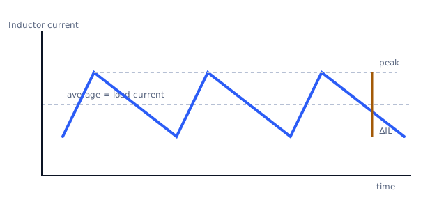
The inductor current is a triangle centred on the load current, so the peak is the average plus half the ripple:
I_peak = I_OUT + ΔIL / 2 I_peak = 2 + 0.2918 I_peak = 2.29 A
This must stay below the part's saturation current. Saturation is not a gentle limit. Past it the core stops storing proportionally and the inductance collapses, so the current ramps far faster than the design assumed. The current can rise steeply within a single switching cycle, which is enough to damage the switch.
Two margins to add. The peak rises at maximum input voltage, because D falls and the off-time lengthens, so compute at your highest VIN, not the nominal. And saturation current falls with temperature, so a part specified at 25 °C has less margin inside a warm enclosure. Vendor guidance commonly suggests a saturation rating around 30 % above the peak; treat the exact figure as the vendor's, and the principle as general.
For this design, with 2.29 A peak, a part rated for saturation at 3.5 A or more is a reasonable starting shortlist.
RMS current, against heating
This is a different rating with a different failure mode, and conflating the two is the most common inductor mistake.
The RMS value of a triangle on a DC level is:
I_RMS = √(I_OUT² + ΔIL² / 12) I_RMS = √(2² + 0.5835² / 12) I_RMS = √(4 + 0.0284) I_RMS = 2.007 A
Almost exactly the load current, because the ripple contributes little in RMS terms at this ripple ratio. That is typical and it is why the load current is a decent first approximation, but it is an approximation and the expression is the honest version.
The RMS rating on a datasheet is a thermal limit, commonly defined as the current producing a specified temperature rise, often 40 °C. Exceed it and nothing collapses suddenly: the part simply runs hotter than its rating assumed, and the rise adds to whatever ambient your enclosure provides.
Saturation says "do not exceed this instantaneously." RMS says "do not exceed this on average or it cooks." A part can have a generous saturation rating and a modest thermal one, or the reverse.
DC resistance, against efficiency
P_DCR = I_RMS² × DCR
With a 25 mΩ part:
P_DCR = 2.007² × 0.025 = 4.028 × 0.025 = 0.1007 W
About 101 mW, in a part the size of a shirt button. Against roughly 6.6 W of output power that is around 1.5 % of the output, before any other loss.
Lower DCR costs size or money, and the trade is usually worth making only up to the point where the inductor stops being the dominant loss.
Core loss is the other half, rising with ripple and with frequency. Vendors publish it as curves or calculators rather than one number, because it depends on material and waveform. At 29 % ripple and 500 kHz it is typically smaller than the DCR loss but not negligible, and the way to get a real figure is the vendor's own tool for the exact part.
Size
The constraint that quietly decides it. Having satisfied the three electrical ratings, you are choosing between parts that differ mostly in footprint and height, and the enclosure usually has an opinion.
The shortlist, summarised
| Parameter | Required | Why |
|---|---|---|
| Inductance | 8.2 µH | gives 29.2 % ripple at 500 kHz |
| Saturation current | above 2.29 A, with margin | peak current, at maximum VIN and hot |
| RMS current rating | above 2.01 A | thermal rise |
| DCR | around 25 mΩ or lower | about 101 mW of loss |
What to check that the arithmetic does not tell you
- The peak at maximum input. Recompute
DandΔILat your highest
input voltage. That is where the peak lives.
- The current during a load step. The loop takes time to respond, and the
inductor current can overshoot the steady-state peak. Datasheets for the controller usually bound this.
- Startup and short-circuit. Current limit defines the real worst case.
An inductor that saturates below the IC's current limit will be driven there during a fault.
- The effective inductance at your DC current. Some parts lose
inductance well before nominal saturation, which raises ripple above what you calculated. The curve is in the datasheet.
What comes next
Lesson 6 moves from the component to the copper: the input capacitor, the loop it closes with the switch, and why that loop is the most important geometry on the board.
Sources and further reading
- Analog Devices: Selecting the Right Inductor Current Ripple — technical article, the 30 % ripple convention and its consequences.
- Texas Instruments: Basic Calculation of a Buck Converter's Power Stage (SLVA477) — application report, inductance, ripple and peak current expressions.
- Analog Devices: Buck Power Stage Design Equations — application note, steady-state power stage relationships.
- Texas Instruments: LM60430 / LM60440 datasheet — datasheet, inductor selection worked against a specific device's current limit.
- onsemi: LC Selection Guide for the DC-DC Synchronous Buck Converter (AND9135) — application note, inductor and capacitor selection for a synchronous buck, from a third vendor.