
Rail-to-Rail Op Amps: What Rail-to-Rail Actually Means
Two separate claims, neither of which promises the rail, and both of which depend on the load.
- Lesson 8 of 10
- Intermediate
"Rail-to-rail" is a phrase that has to be unpacked before it can be used, because it is two different claims wearing one name, and neither of them is the claim most people hear.
The claim most people hear is that the part works from 0 V to the supply voltage on both ends, at both inputs and output, under any conditions. No amplifier does that. What the good ones do is get close enough that the remainder is a number you can budget for, and the purpose of this lesson is to find that number.
Quick answer. Rail-to-rail input and rail-to-rail output are separate specifications with separate mechanisms, and a part can have one without the other. Rail-to-rail output means the output can approach each supply, with the remaining headroom set mainly by the load current. Rail-to-rail input means the input common-mode range covers the whole supply span, which is usually achieved with two input stages and a handover region between them where the offset voltage steps.
Two claims, two mechanisms
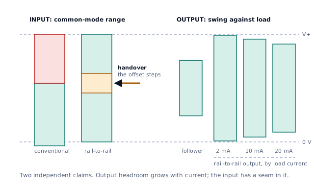
The input and the output of an op amp are different circuits with different problems, which is why the two claims are independent.
The output problem is how close a transistor can pull a node to a supply while carrying current. The input problem is how close a differential pair can sit to a supply and still work. Solving one does nothing for the other, and a part specified as rail-to-rail output with a conventional input stage is a perfectly normal and often sensible product.
The abbreviation RRIO means both. RRO alone means output only. Read which one the datasheet actually claims, including on the front page, where the marketing summary is sometimes looser than the specification table.
Output: the headroom is a function of the load
A traditional output stage is an emitter or source follower, which can never get closer to a rail than its own drive requirement. That is the architecture that stops a volt or so short, and it is not what gets called rail-to-rail.
A rail-to-rail output stage uses common-emitter or common-source devices instead, so the output transistor sits directly between the output node and the rail. Now how close you get depends on how much voltage drops across a conducting transistor, which depends on how much current it is carrying.
That dependency is the whole story, and it can be made quantitative. Suppose a datasheet specifies 150 mV of headroom when sourcing 10 mA. Treat the output device as a resistance:
Rout ≈ 150 mV / 10 mA = 15 ΩThen at other currents, approximately:
at 20 mA:  20 mA × 15 Ω = 300 mV
at  2 mA:   2 mA × 15 Ω =  30 mV
On a 3.3 V supply, a load pulling 20 mA in both directions leaves a usable output range of 3.3 − 0.3 − 0.3 = 2.7 V, which is 82 % of the supply. The same part driving 2 mA leaves 3.24 V, or 98 %. One part, one supply, two very different answers, decided by the load.
Two honest caveats on that arithmetic. A real output stage is not a pure resistance, so the linear extrapolation is a planning estimate and the datasheet's headroom-versus-current curve is the authority. And the on- resistance of the output device rises with temperature, so the headroom you measured on a warm bench is not the worst case.
It also cuts the other way, which is a genuinely useful thing to know. A general-purpose part that is not rail-to-rail can still get extremely close to the negative rail into a light load. The LM358 family is specified to pull its output below 20 mV of the negative supply with a load of 10 kΩ or less returned to that rail, which is better than many people expect from a part nobody would call rail-to-rail. Ask it to sink more current and the behaviour changes completely: a weak internal current sink handles the first few microamps, and beyond roughly 12 µA at 200 mV the output needs a different internal device that does not engage until the output is several hundred millivolts up.
The lesson is not that the LM358 is secretly rail-to-rail. It is that "how close to the rail" is not a property of the part. It is a property of the part and the load together, and any claim stated without a load current is incomplete.
Input: two stages and the seam between them
Getting the input common-mode range to cover the whole supply is usually done by building two input stages instead of one.
A PNP or PMOS pair handles the lower part of the range, from below the negative rail up to roughly a volt and a half short of the positive one. An auxiliary NPN or NMOS pair handles that last stretch to the positive rail. Between them there is a handover region where responsibility passes from one pair to the other.
The two pairs are separate pieces of silicon with separate offsets. So as the common-mode voltage sweeps through the handover, the input offset voltage does not drift, it steps. On a datasheet this shows up as a discontinuity in the plot of offset voltage against input common-mode voltage, and it is the most informative plot in the whole document for anyone considering a rail-to-rail input part for a precision job.
Three consequences:
- In a precision DC circuit the step is a real error. If your signal's
common-mode voltage crosses the handover, part of your transfer curve has one offset and part has another. Calibration at one point does not fix the other.
- With a moving common-mode voltage it also becomes distortion. A
follower or a non-inverting stage puts the signal itself on the common-mode input, so the signal sweeps through the handover on every cycle and picks up a non-linearity that no amount of loop gain removes.
- Some parts avoid it entirely. An internal charge pump can supply the
input stage from a voltage above the positive rail, which lets a single pair cover the whole range. Those parts are specifically marketed on having no crossover, and it is one of the few cases where the marketing phrase describes something structural.
The escape route costs nothing when it is available: arrange the circuit so the common-mode voltage does not move. An inverting stage or a transimpedance amplifier pins its input node at a fixed voltage, so the handover region is simply somewhere you never go. This is the quiet advantage of the inverting topology noted back in lesson 2.
What the phrase does and does not promise
| Claim | What it means | What it does not mean |
|---|---|---|
| Rail-to-rail output | the output stage can approach both rails | that it reaches them, or that headroom is load-independent |
| Rail-to-rail input | the common-mode range spans the supplies | that offset is constant across that span |
| RRIO | both of the above | that you can ignore either |
| "Within 100 mV of the rail" | true at the stated load | anything at all at four times that load |
| Specified at 25 °C | true at 25 °C | the hot or cold limit |
Choosing with this in mind
Decide what you actually need, because rail-to-rail capability is not free. It is paid for in some combination of offset, noise, distortion near the rails and quiescent current.
- Need the output to reach near a rail, with a known load? That is a
rail-to-rail output requirement and the headroom arithmetic above sizes it.
- Need the input to sit near the positive rail, as in high-side sensing?
That is a rail-to-rail input requirement, and the handover region matters only if your common-mode voltage moves through it.
- Need neither, because the stage has gain and the signal sits mid-supply?
Then a conventional part may be more accurate and cheaper, and the rail-to-rail label is a distraction.
Our own front end from earlier lessons is in the third category at the input, where the signal sits near 0 V, and in the first at the output, where the full scale of 2.38 V on a 3.3 V supply leaves nearly a volt of headroom. Neither end is demanding. That is worth noticing, because it means the right part for this circuit is chosen on offset and bias current rather than on a label.
What comes next
Lesson 9 leaves the DC and input questions behind and looks at what happens when you connect the output to something capacitive, which is the point at which an amplifier can stop being an amplifier and become an oscillator.
Sources and further reading
- Texas Instruments: When to Use an Amplifier with Rail-to-rail Inputs, and What to Watch Out for (SSZTB56) — technical article, the two-stage input topology, where the handover sits, and the offset discontinuity it produces.
- Texas Instruments: Application Design Guidelines for LM324 and LM358 Devices (SLOA277B) — application note, how output low voltage depends on load current and termination in a non-rail-to-rail part.
- Texas Instruments: OPA320 and OPA2320 datasheet — datasheet, a charge-pumped input stage presented as the way to remove crossover distortion.
- Microchip: AN682 Using Single Supply Operational Amplifiers in Embedded Systems — application note, why output and input range become binding constraints on a single low supply.