
Slew Rate: The Op-Amp Limit That Gain-Bandwidth Does Not Explain
The same amplifier is good to 1 MHz with a small signal and to 40 kHz with a large one.
- Lesson 4 of 10
- Intermediate
Gain-bandwidth product predicts what happens to small signals. It says nothing useful about large ones, and the difference between those two regimes is not a detail. The same amplifier can be good to 1 MHz with one signal and to 40 kHz with another, with no change to the circuit.
Quick answer. Slew rate is the fastest the output can change, in volts per microsecond, and it is a hard limit set inside the amplifier rather than a gradual roll-off. A sine wave of amplitude Vpeak at frequency f needs a slew rate of at least 2π·f·Vpeak. If the amplifier cannot supply it, the output stops being a sine wave and becomes a triangle, regardless of how much gain-bandwidth the part has left.
Two different limits, two different mechanisms
Bandwidth limiting is a shortage of gain. The loop still works, it just has less authority than it needs, so the output comes out smaller and later. The waveform shape survives.
Slew limiting is a shortage of current. Inside the amplifier, the input stage produces a current proportional to the input difference, and that current charges the internal compensation capacitor. The output voltage follows the voltage on that capacitor. When the input difference is large enough, the input stage delivers all the current it has, and the capacitor charges at a rate that cannot increase no matter how much larger the input difference becomes. That ceiling is the slew rate.
Three things follow from that mechanism, and they explain most of the confusion around the parameter.
- While an amplifier is slewing, it is not in control. The output is
moving at its maximum rate, not at the rate the feedback is asking for. The loop is effectively open and the two inputs can be far apart.
- The input difference has to be substantial to get there. The virtual
short has to be abandoned before full slew rate appears at all, which is exactly why slew rate and small-signal bandwidth are unrelated.
- The datasheet number has test conditions. It is normally measured at
unity gain with a large step, and the rate your circuit actually achieves can be lower. Some modern parts also include circuitry that boosts the slew rate once the input difference exceeds some threshold, which means the response is not a single straight ramp and the headline figure may only apply to large excursions.
What a sine wave demands
A sine wave is steepest as it crosses zero. For an output of amplitude Vpeak at frequency f, the maximum rate of change is:
SR required = 2π · f · VpeakTake an output of 2.0 V peak at 1 kHz:
SR = 2π × 1 000 × 2.0 = 12 566 V/s = 0.0126 V/µsNothing on the market struggles with that. Now the same amplitude at 100 kHz:
SR = 2π × 100 000 × 2.0 = 1 256 637 V/s = 1.26 V/µsA hundred times more, because the requirement scales directly with frequency. It scales directly with amplitude too, which is why a signal that is clean at 200 mV can tear itself apart at 2 V.
Full-power bandwidth, and the factor of 25
Turn the relationship around and you get the highest frequency at which an amplifier can produce a given amplitude without slewing:
f = SR / (2π · Vpeak)For a part with a slew rate of 0.5 V/µs asked for 2.0 V peak:
f = 500 000 / (2π × 2.0) = 39 789 HzSo 39.8 kHz. If that same part is specified at a gain-bandwidth product of 1 MHz, then at unity gain its small-signal bandwidth is 1 MHz and its large-signal limit is 39.8 kHz. The ratio is about 25.
That is the whole lesson in one pair of numbers. Both figures are honest, both come from the same datasheet, and choosing the wrong one gives an answer that is wrong by a factor of twenty-five.
Two cautions on that calculation. The classical relationship treats the slew rate as a single number and marks the point where the output can no longer keep up at all. Distortion starts rising well before that point, so a design that needs low distortion should be kept comfortably below the full-power bandwidth rather than just inside it. And for parts with slew boost, the simple formula can describe two different regions rather than one.
Telling them apart on a scope
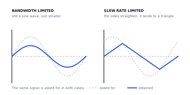
| What you see | Bandwidth limited | Slew rate limited |
|---|---|---|
| Shape of a sine output | still a sine | sides straighten, tends to a triangle |
| Effect of reducing amplitude | amplitude falls in proportion, shape unchanged | distortion disappears below a threshold |
| Effect of reducing frequency | amplitude recovers gradually | distortion disappears fairly abruptly |
| Step response | rounded, exponential-looking edge | straight ramp with a constant slope |
| Depends on closed-loop gain | yes, strongly | not directly |
The second row is the quickest test on the bench. Halve the amplitude. If the distortion vanishes while the frequency is untouched, the amplifier was slewing. If the output simply gets half as big and looks the same as before, it was running out of bandwidth.
The step response is the clearest tell of all. A straight edge with a constant slope is not something a linear system does. Measure that slope and you have measured the slew rate of your circuit, under your conditions, which is a more useful number than the one in the datasheet.
Does it matter in our front end?
Our sensor amplifier has a small-signal bandwidth of 8.4 kHz and a full-scale output of 2.38 V. The slew rate required to produce a 2.38 V peak sine at 8.4 kHz is:
SR = 2π × 8 400 × 2.38 = 125 613 V/s = 0.126 V/µsAny general-purpose amplifier supplies that comfortably, so slew rate is not the binding constraint here and pretending otherwise would be dishonest. The gain-bandwidth product gave up first.
That is worth stating plainly, because the useful skill is not knowing that slew rate exists. It is knowing which of an amplifier's limits is the one your circuit will actually meet, and in a slow high-gain front end it is almost never this one. It becomes the binding limit in the opposite kind of circuit: low gain, large output swing, fast edges. A buffer driving a few volts at a few hundred kilohertz will meet slew rate long before it meets anything else.
What comes next
Lesson 5 goes back to the slow, high-gain case and asks a different question: with the bandwidth settled, how accurate is the reading? The first answer is input offset voltage, and the number it produces is larger than most people guess.
Sources and further reading
- Texas Instruments: Ramping Up on Slew Rate (SLOA332) — application note, where slew rate comes from inside the part and why the in-circuit value differs from the datasheet value.
- Texas Instruments: Full Power Bandwidth and Op Amp Distortion (SDAA309) — application note, the limits of the classical full-power bandwidth relationship and what distortion does near it.
- Texas Instruments: Understanding Operational Amplifier Specifications (SLOA011) — application report, slew rate among the other AC parameters and their test conditions.
- Microchip: AN723 Operational Amplifier AC Specifications and Applications — application note, how the AC specifications limit a real circuit.